Perhaps the final post about the good old nRF24L01+ and the shady Chinese suppliers that tend to optimize all freakin’ bits and pieces. This time I will tell how to create a simple RF calibration station to verify the modules are properly operational and how to manually fix those that are not.
The problem
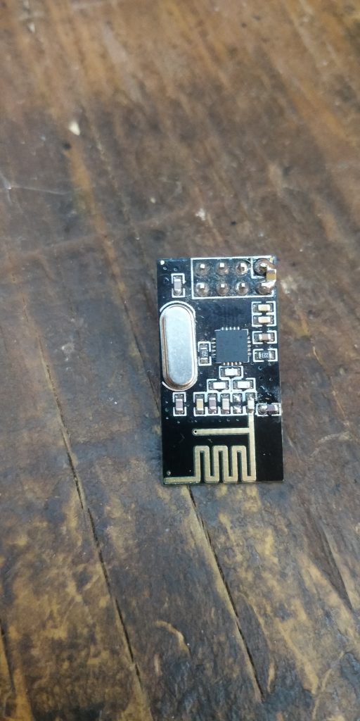
So, as I’ve written before, nRF24L01+ can be very optimized or even if the silicon isn’t fake, it may have some ‘magic finger’ problems. By the end of holidays in Russia, a fresh batch of nRF24L01+ modules arrived to my joy. And to my frustration, none of them worked out of the box.
While I was waiting, I managed to get SI24R01-like COB fakes play nicely with my current setup, by patching ugly mysensors. But that’s another story for another post. What was wrong with those ones? It turned out to be that very same ‘magic finger’ problem. But this time so severe – that none of the modules worked with mysensors, though they flashed via my rf24boot bootloader with no issue. So, what was the problem?
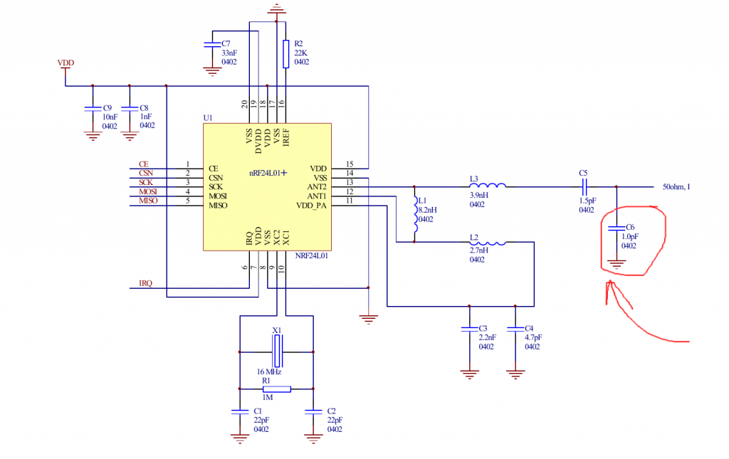
The pitfall was the radio speed. For bootloading I use 2Mbps, to get things done faster. For mysensors network, I use 250Kbps for better range. Turns out that 250Kbps speed is most sensitive to how the antenna is designed. And the modules I received this time were totally screwed. Adding a 1pF capacitor helped a little, but they were still underperforming and loosing packets. Touching the antenna still helped a little, but picking the right capacitor required some precise measurements. 2.4Ghz spectrum analyzer? Well, I ain’t Elon Musk with a few millions $$$ at his disposal. Perhaps, I can make some cheaper testing rig? Or perhaps it has been done before?
Reworking nRFDoctor
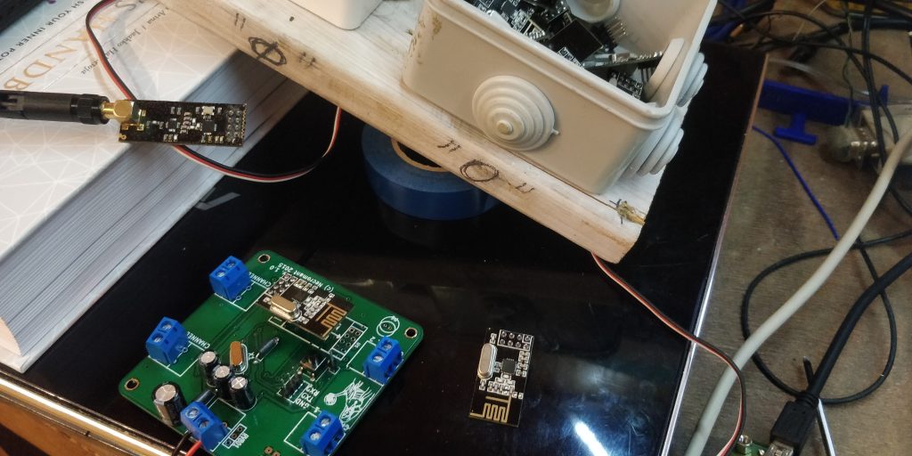
A few folks on mysensors forums have implemented precisely that. A rig that sends packets to the gateway, requesting ACKs and calculates some statistics. They use an LCD to display the results, but I decided to just pipe all the data to HomeAssistant for display instead and use one of my existing boards as a test rig. Any board with MCU supported by mysensors and an nRF24L01+ would do, though I’d take care to make sure that there are no power issues.
My app exposed 4 child sensors: The current packet number sent to gateway (can be used as a progress meter), successfully delivered payloads, TX failures and ECHO’s that didn’t arrive (TX failures+RX failures). I added the following card to the hass’ lovelace UI:
type: vertical-stack
cards:
  - type: gauge
    entity: sensor.red_wisp_radiotester_250_0
    min: 0
    max: 100
    name: Testing Progress
    unit: '%'
  - type: sensor
    entity: sensor.red_wisp_radiotester_250_1
    unit: '%'
    name: Link Quality
  - type: sensor
    entity: sensor.red_wisp_radiotester_250_2
    unit: packets
    name: TX Failed
  - type: sensor
    entity: sensor.red_wisp_radiotester_250_3
    unit: packets
    name: RX Failed
That in turn created a nice user interface that I could use.
In the firmware I also made parent Node ID static, since I didn’t want to measure connection quality of anything inbetween.
#define MY_PARENT_NODE_ID 0
#define MY_PARENT_NODE_IS_STATIC
Since the testing rig will generate a bunch of traffic and useless sensor data that I don’t want to store in hass db, I also adjusted my homeassistant’s settings to ignore the data from the testing rig.
recorder:
  exclude:
    - sensor.red_wisp_radiotester_250_0
    - sensor.red_wisp_radiotester_250_1
    - sensor.red_wisp_radiotester_250_2
    - sensor.red_wisp_radiotester_250_3
Testing and calibrating the junky modules
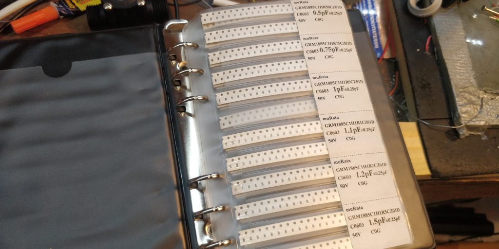
Once we’ve done it, we can measure precisely how bad are those modules. But to actually fix it, we’ll need a soldering iron and some capacitors of different values. My experiments showed me, that I usually needed something between 1pF and 2.2pF.
The process of calibration was simple. Insert the module in the rig and press reset.
- Flash the board with the testing software
- If the module’s on the network, wait for the first 2-3 measurement cycles. If we’re way below 90-95% successful packet deliveries or the device doesn’t appear on the network at all, proceed to step 3.
- If the module’s not on the network, cover the PCB antenna with kapton tape and touch it. It apeared and working properly? Proceed to step 4.
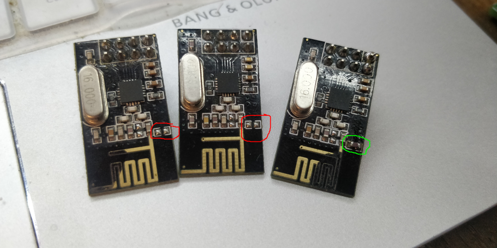
- Add a 1pF cap and test again. If that didn’t work, add 1.5pF cap instead. You got the idea. Binary search, remember? Once your finger on the PCB antenna instead of improving successful deliveries starts spoiling them, you’ve reached the sweet spot. The closer you put your finger to the PCB traces, the more capacitance you add, so you can use it as variable capacitor if you are gentle 😉
- Once you are satisfied with the results, throw the module in the “Works fine” batch and proceed to the next one.
Results
My guess was that the modules from the same batch will all require the same value capacitor for proper operation. That was true for leftover modules from the previous batches that required the biggest 2.2pF capacitors but worked with no issues afterwards.
The weird COB chips from this post to my surprise worked with no issues and needed no capacitors on the antenna for proper operation.
But the last batch I received was complete trash, despite being compatible with the genuine chips. The capacitance I had to add for proper operation was varying from 1pF to 1.8pF and each module took 2-3 iterations to fix.
The ‘okay’ modules from previous batches that had no capacitor on them worked properly even without any caps and my finger wouldn’t improve their performance. Perhaps it’s ‘builtin’ in the PCB during manufacturing?
From what it looks to me, somebody decided to save a few cents on the impedance control and the antenna part turned out to be crap.
All in all selecting a proper capacitor for the antenna got me 90-95% successful packet delivery rate. Adding a 1uF cap at the very power pins of the module further improved in to 99-100%! Epic win!
Lessons to learn
The obvious lesson to learn is to pick the suppliers. But that is becoming increasingly difficult. The above procedure is okay and fun for a hobby project, but if I were to ship a few thousand of devices with those modules I’d go nuts by the end of the first hundred. Perhaps the only solution here is put the actual chip on YOUR PCB, and manufacture it with impedance control and other stuff, unless you’re a fan of manual labor.
If you add a bigger ceramic cap across the power input it will help further. I typically use 47uF for those type of boards and 100uF for the PA/LNA modules. Also the ‘red’ PCB modules from Ebyte (irCDEbyte) seem to be better built and give less problems than the no-name ones like you show here.
Connection quality must be good too so either really good crimped dupont or better yet solder everything if possible. Power supply must be smooth and have enough capaciity to quickly react to the short transmission times. Just about every bad node I have turns out to be connections or power supply!
My tests show that a few small ceramic caps (~1-10uF) in parallel give best results (My guess – due to lower ESR). But I have a more or less decent power supply, perhaps in your case bigger caps would indeed help better.
Nice post.
I think the only real solution these days if you are trying to make something usable is to get the ebyte modules from “cdebyte” on ebay. I literally cannot trust any other supplier to have genuine nrf and properly matched rf network / pcb antenna.
I think it’s only a few dollars more if you buy a handful of modules vs cheapo ones, but what is one’s hair loss and mental health worth 😉
This is very interesting. Can you please share the source code? I am only getting a few metres range from nRF24L01’s with 10uF ceramic capacitors between 3.3v and GND. I need to start being more systematci with my testing. Thanks