Yet another post about smart home. This time I’ll be integrating Nice Flor-S gate remote control with HomeAssistant, using EspHome, RTL-SDR, and a relay board from Aliexpress.
Getting stuff apart
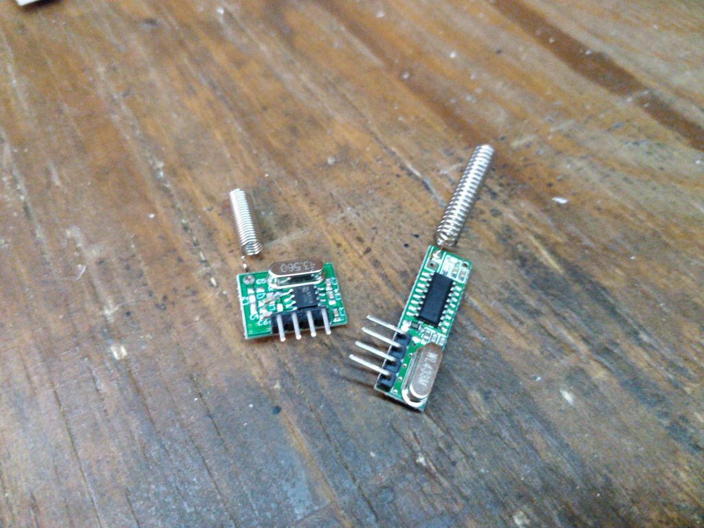
So, I had those automatic gates for many years, even from times before HomeAssistant came to be. Once I had it setup, I wondered if how to make these two work along with each other. So I started by taking apart one of the spare remotes to see what’s inside and what could be done.

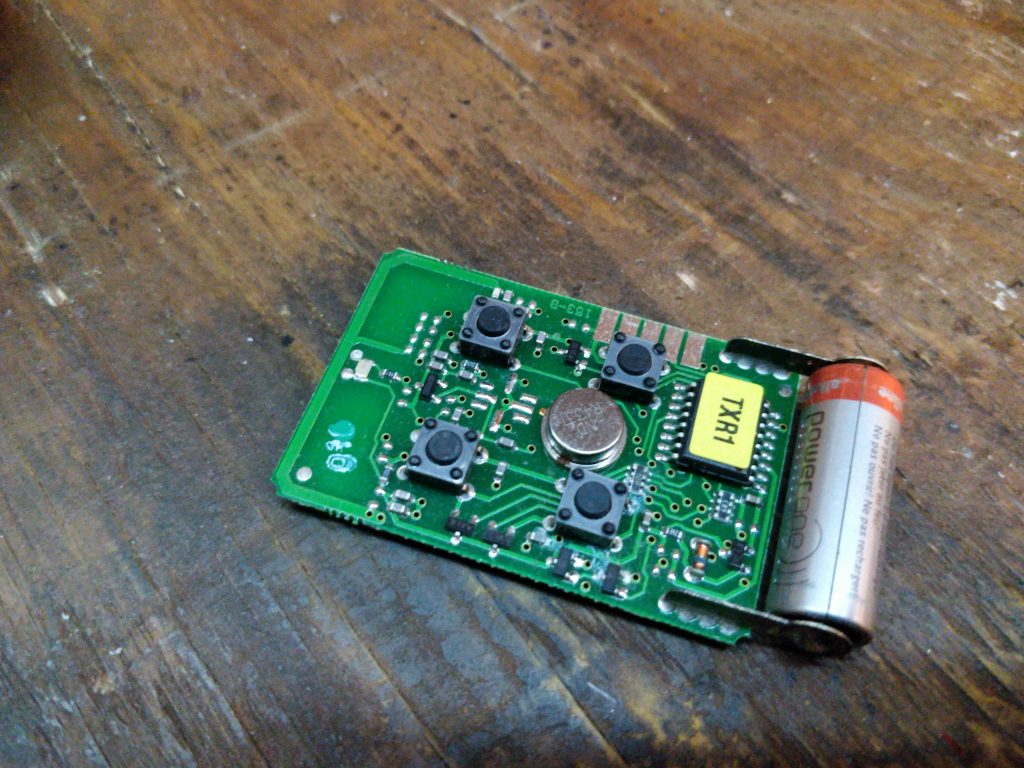
Inside was a 433 radio circuit along with a Motorola HC08. Well, that was a blast from the past, I used to write assembly for those back in my student days.
Plan A. Let’s fire up RTL-SDR
So I popped in my RTL-SDR dogle, fired up gqrx and saw the transmission happening on the 433Mhz beautifully on the waterflow plot. Now, perhaps I can decode it?
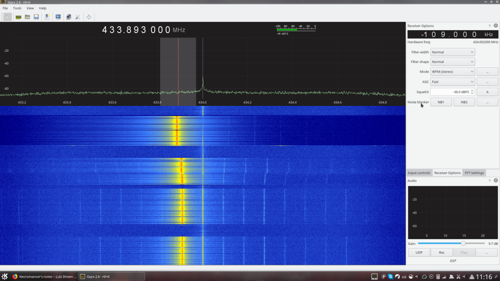
The plan was: decode the protocol and then emulate the dongle using a cheap 433Mhz RF-GPIO boards from our well-known electronics junkyard called Aliexress.
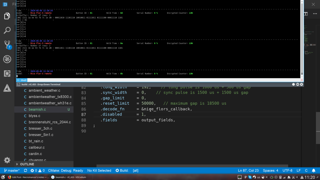
For this purpose I fired up rtl-433 and… Saw nothing. The program managed to detect that there was something happening, but no protocol decoder for nice flor-s existed.
I googled the internet and found a Russian site that documented pretty well the protocol and the possible attack on those gate automation. Yikes!
The protocol was not fully documented, but the article still gave me a quick start. I created a proof-of-concept plugin for rtl-433 that could decode the buttons being pressed. With some luck I could also manage to dump timecodes (e.g. how long the button was pressed at a time). But what next?
The problem was that the protocol was only partially documented. With the documentation I found the only thing I could decode – button id and timecode. The rest would be a complete mystery. I could give a try and dump the HC08 MCU firmware? Something told me that they had readback protection in place, no worth trying.
Perhaps, running a small automation rig to dump all possible timecodes/serial number combinations for my remote and later giving a spin to analyze it? I was sorry to abandon a fun reverse engineering quest, but sometimes you just have to. That fun required too much of a critical resource I had so little: time.
Plan B. Let’s just rig a few relays to ‘press’ the buttons
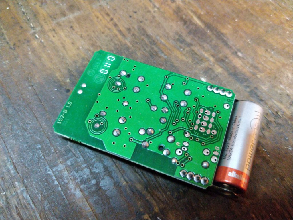
I carefully examined the remote control with a multimeter. It is powered by a small 12V battery. The +12V power rail of the battery is connected directly to four buttons. When no button is pressed the whole circuit is completely unpowered. So, we could use any transistor/mosfet to do the job. But that would mean laying out a board and using even more of the precious resource called ‘time’. So instead I opened up Aliexpress and ordered a few 4-channel relay modules with good old esp8266. Some LC-tech company makes those in 5V and 12V versions.
At this point I had to put aside the project and wait for a month or so for the relays to arrive.
Getting started with 4-channel LC-Tech relay modules
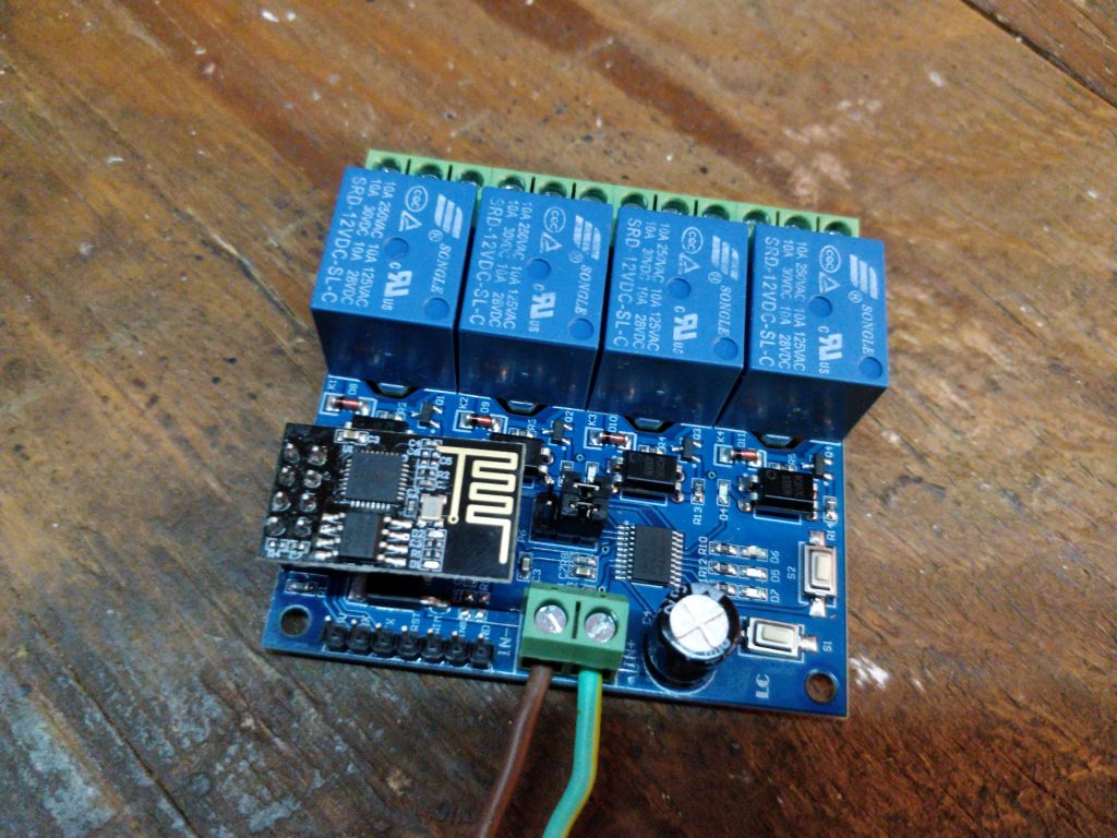
The engineering solutions here were, well, mixed. On one hand the board had optocouplers isolating the relays and even had the cutouts on the board to improve isolation (Just in case the relays would be used to switch mains voltage). But on the other hand, the power circuit was the dumbest possible. Perhaps you’ve read my recent post about me being furious about linear dropouts being hot as hell at the esp-14 devboard. Well, this board had pretty much the same issue: The input is 12 Volts. Next they make 5V using a huge linear regulator, and next they make 3.3 volts using another one. Energy ‘efficiency’ at its best. The power supply part will get pretty hot if you don’t use power saving mode on esp8266 wireless. Besides, those 5mm screw terminals suck when it comes to mains voltage – the cable is to likely to get loose (unless you tin it).
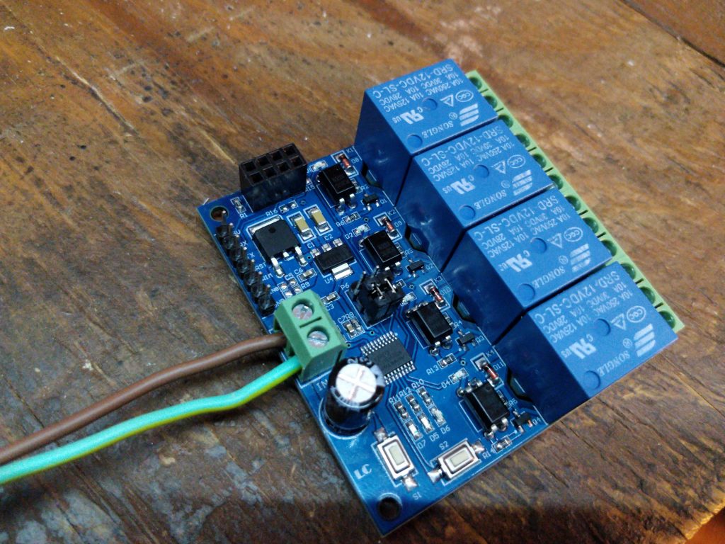
The weirdest part of the whole thing was the Nuvoton n76e003at20 microcontroller. It’s the first time I came across one of these. The ESP8266 is connected via UART to this weird thingie. 2 buttons, three LEDs and four relays are connected to this micro-controller. Judging by the datasheet it’s a yet another 8051 MCU. Perhaps I’ll do another post sometime later about these MCUs, but for now I used the stock firmware.
As for ESP8266 I never took the time what the heck was that ‘ai cloud inside’, I just quickly flashed a ESPhome-based firmware.
With ESPhome we have two options to hook these relays. We can use a UART switch component. Or we can write our own custom one. Since I’ve noticed a thing about the protocol, I decided to take the custom component way.
According to the docs, the UART protocol looked like this:
 Open relay  1:A0 01 01 A2
 Close relay 1:A0 01 00 A1
 Open relay  2:A0 02 01 A3
 Close relay 2:A0 02 00 A2
 Open relay  3:A0 03 01 A4
 Close relay 3:A0 03 00 A3
 Open relay  4:A0 04 01 A5
Close relay 4:A0 04 00 A4 - Byte 1. A0 – start of the packet
- Byte 2. Relay ID (1-4)
- Byte 3. Relay state 0/1
- Byte 4. Checksum. Looks like the sum of the first three bytes.
So, the code to drive all similar relay modules with esphome would look somewhat like this:
#include "esphome.h" using namespace esphome; class LCRelay : public Component, public UARTDevice, public switch_::Switch { public: int relayId; LCRelay(UARTComponent *parent, int relay): UARTDevice(parent) { relayId = relay; } void setup() override { } void write_state(bool state) override { uint8_t msg[4]; msg[0] = 0xA0; msg[1] = relayId; msg[2] = state; msg[3] = msg[0] + msg[1] + msg[2]; /* There are no ack/nack packets. Let's send the payload twice to be sure */ this->write_array(msg, sizeof(msg)); this->write_array(msg, sizeof(msg)); publish_state(state); } }; |
Now, to hook this in our yaml config. The minimal config would look like this.
substitutions: devicename: "gatekeeper" esphome: name: $devicename platform: ESP8266 board: esp01_1m build_path: build/gatecontrol includes: - lcrelay.h uart: id: uart baud_rate: 115200 tx_pin: GPIO1 rx_pin: GPIO3 switch: - platform: custom lambda: |- auto r1 = new LCRelay(id(uart), 1); auto r2 = new LCRelay(id(uart), 2); auto r3 = new LCRelay(id(uart), 3); auto r4 = new LCRelay(id(uart), 4); App.register_component(r1); App.register_component(r2); App.register_component(r3); App.register_component(r4); return {r1, r2, r3, r4}; switches: - name: "${devicename} Relay 1" id: relay1 internal: true - name: "${devicename} Relay 2" id: relay2 internal: true - name: "${devicename} Relay 3" id: relay3 internal: true - name: "${devicename} IceShard Power" id: relay4 internal: true |
As you can see, I’ve made all relay switches internal. The trick here is that to drive the nice flor-s buttons we’ll need to turn relay for ~1 second and than immediately turn them off. We can’t just do delay(1000) in our C++ code, since the watchdog will kick in. The clean way (If I got the esphome idea correctly) would be handling that in yaml config. Just add the following to the switch section for each of the relays.
- platform: template name: "${devicename} Main Gates" icon: mdi:gate lambda: |- if (id(relay1).state) { return true; } else { return false; } turn_on_action: - switch.turn_on: relay1 - delay: 1s - switch.turn_off: relay1 turn_off_action: switch.turn_off: relay1 |
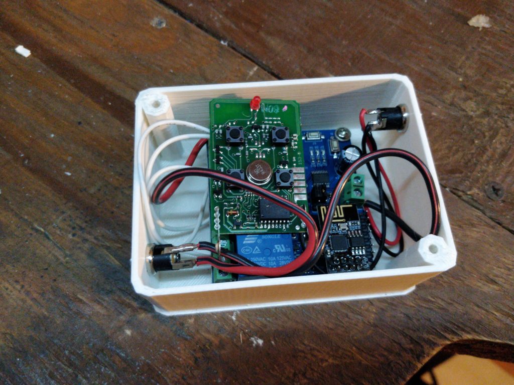
Putting it all together
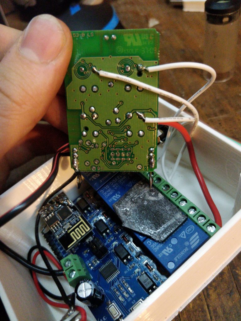
Once the firmware was up and running I printed a plastic box to house all the goodies and soldered the wires to the remote. I only use three buttons, so I hooked the remaining relay to turn on and off 12 volts on a barrel jack outlet.
The good stuff
As usual, the artifacts for this project are up for anyone’s interested to download and play with, namely:
Btw, full support for Flor-S remotes has been integrated as protocol 169 in rtl_433.
Thanks a lot, Samuel! These are really good news, I’ll check it out.
Looking at your code: https://github.com/merbanan/rtl_433/blob/master/src/devices/nice_flor_s.c
This is basically as far as I could get with patching and that article from phreakerclub. Thanks implementing those cleanly up and mainlining. Still, rolling code algorithms are missing and I doubt anyone will care to reverse these in the near future.
Does you still use the battery on the remote ? I don’t understand why there is only3 wire on the remote. Do you have a 4th cable with GND to make the connection ?
Sorry for the long wait, akismet caught your comment as spam. If you use a multimeter, you’ll see that the buttons connect +12V power rails to different nets. So pressing a button basically supplies power AND tells MCU what to send at the same time. Next,
I just connected GND<-->GND, and relays supply +12V to different buttons. No battery needed. That’s all.
Hallo,
I was able to integrate the standard version with 4 relays in homassitant, thanks for that. The button version interests me as well.
The alternative firmware of the onboard 8051 “adds buttons and RGB Leds” according to your explanation but there is no wiring diagram added for clarification or am I misunderstanding and the LEDs and the two switches on the PCB are reused?
Regards
To drive leds and buttons, you need to flash the companion MCU. It’s ARM-based. The firmware is up on my github: https://github.com/nekromant/lctech-relay-altfw
All the pins are in the code.
https://github.com/flipperdevices/flipperzero-firmware/blob/96cad511e3aae58308785b47deeb6269b6442659/lib/subghz/protocols/nice_flor_s.c
Hi, Sems that the protocol was decripted. I’m also interested in the remote clone. Can you help (I’m not so good with arduino) Thank you for this article. https://github.com/flipperdevices/flipperzero-firmware/blob/96cad511e3aae58308785b47deeb6269b6442659/lib/subghz/protocols/nice_flor_s.c