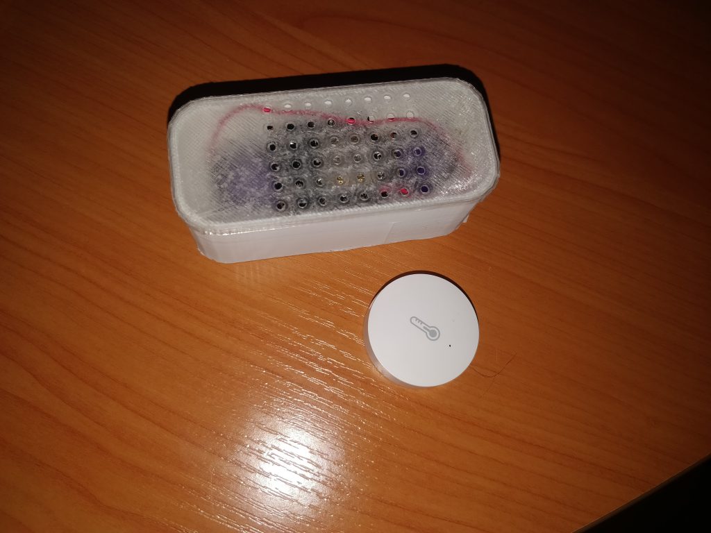
Here’s another one of my notes about DIY smart home solutions. This time I decided to find a better replacement for Aqara temperature/humidity sensors using a devboard with a esp8266+stm8 (esp-14s module) and a homebrew esphome-based firmware. With aqara’s stock sensors I didn’t like their crappy precision and no way to change the sensor polling time. So, why not get almost all of those wishes fulfilled with a ready-made esp8266 module? Besides, nearly no price difference. Well, that’s what this post is about.
What’s wrong with the stock sensors? And what are we going to do about it?
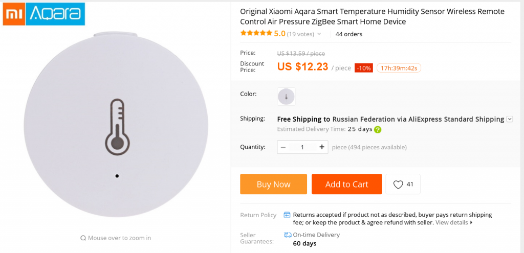
So what’s the problem with Aqara’s sensors? First one, the price of 12 bucks each from aliexpress. The device looked way too simple to me to cost that much. Second, for my DYI smarthome I needed to monitor atmospheric pressure, as well as lux. Aqara’s sensor couldn’t do that.
Finally, since I don’t use Xiaomi crappy smart home app, prefering a local HomeAssistant instance, I had a way bigger choice of hardware.
So I instantly remembered the good’ old esp8266 platform, I worked for a while with. I even used to develop a (now abandoned firmware) called frankenstein. I later hooked it to the NextCloud Sensorlogger. That was back in the dark times HomeAssistant didn’t exist or was not that mature.
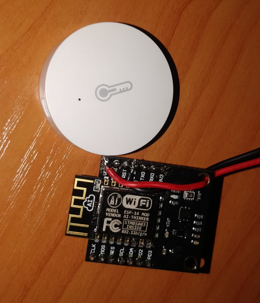
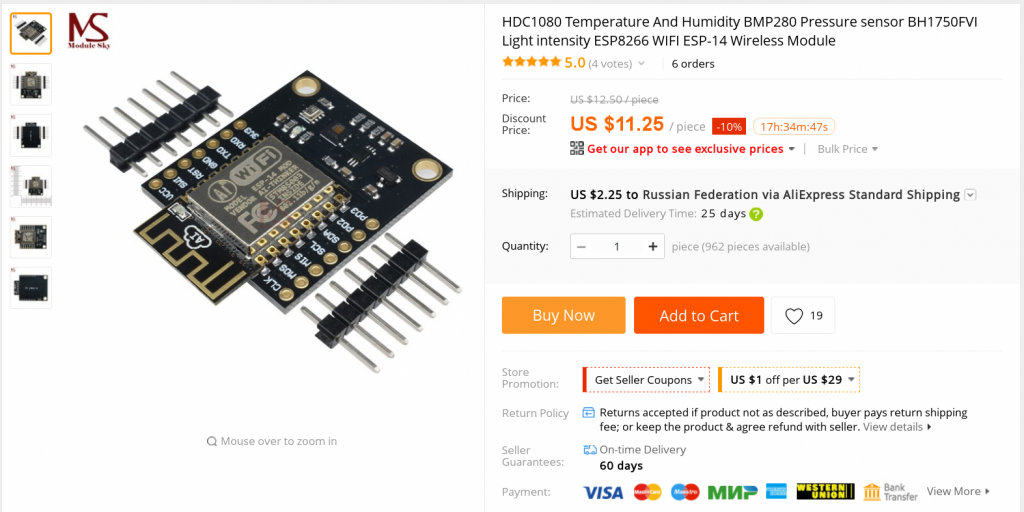
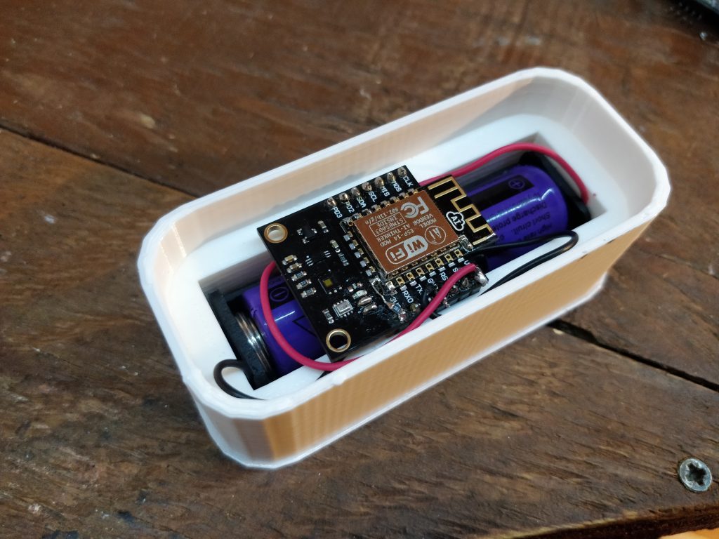
So I dug into the junk and took out a ESP-14 development board I picked up a few years ago. (It’s a weird STM8 and ESP8266 hybrid), that had all the necessary sensors. A quick search over aliexpress showed up the board were still on sale on aliexpress for a price a little higher than Aqara Sensors. But, after all – more sensors, right?
What’s the plan?
So the plan was dumb and simple
- Get the firmware ready
- Test it (And fix bugs)
- Connect with HomeAssistant
- If it works, get a 3d-printed case with a battery slot and order another bunch of those boards.
- PROFIT!
Flash it! (ESPHome)
Due to what’s inside, we have to flash to microcontrollers. ESP8266, в that I flashed with EspHome and an STM8S, that had all the sensors connected to. What we’ll need.
- A USB<–>UART TTL converter (to flash esp8266)
- STM8 programmer (A cheap Chinese stlinkv2 would do)
- Windows machine and an IAR demo (to compile the STM8 firmware)
On the internets I found an IAR project for the STM8 that had all the necessary code to get the sensor readings via STM8 and post them via modbus. I had no ModBus anywhere, so I modded the firmware to output all data via simple UART packets.
To compile it you’ll need Windows and IAR (Trial, code-limited would do. SDCC won’t help, original firmware has a huge bunch of C++ code). Besides, I learned that in almost 10 years IAR hasn’t change a bit: It’s still ugly, buggy as hell, and crashed more times than I can remember.
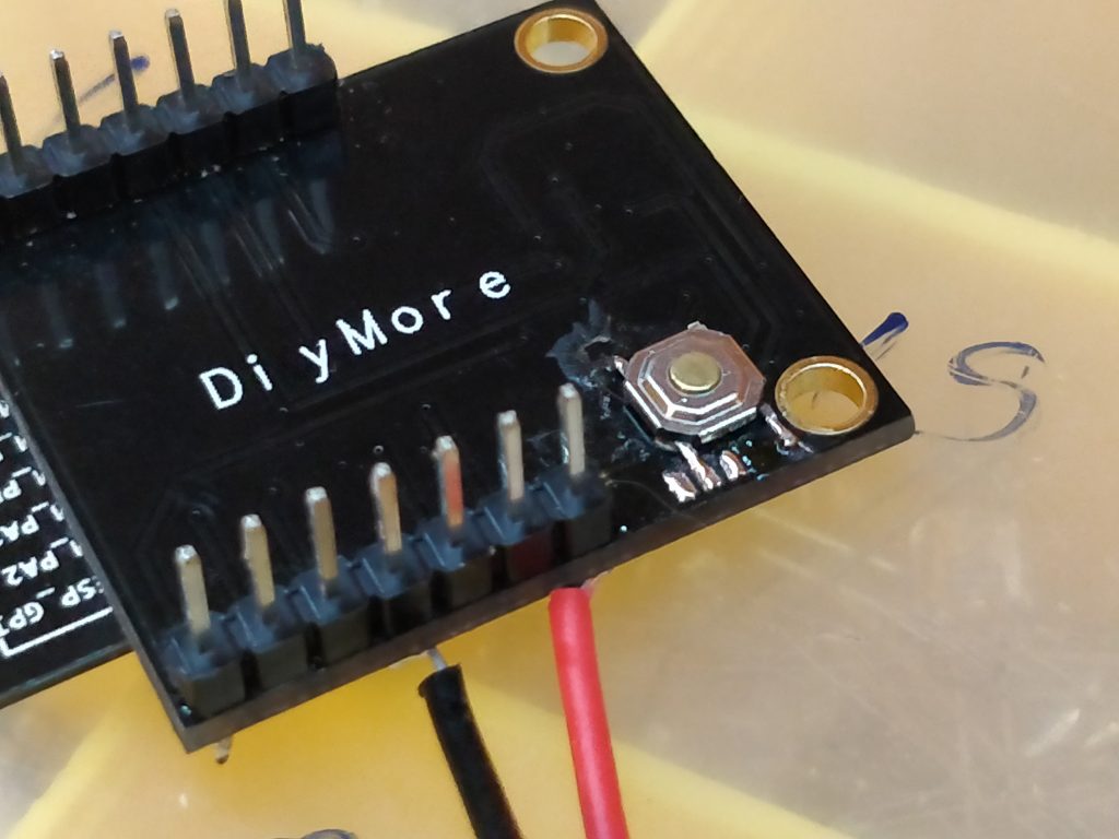
Next we’ll need to flash ESP8266, and here there’s another trap from the board developers: To flash esp8266 you have to short GPIO0 to “0” and supply power. But GPIO0 is only available on the small pad at the bottom. I ended up poking with a multimeter and adding a small button that shorts the middle pad to the ground plane.
So, how to flash this stuff? (Messy instructions)
Here are some quick instructions to connect and flash pieces of the puzzle. I assume that the reader already knows some basic stuff about STM8 and ESP8266, so I’ll just describe the connectivity. Let’s start with STM8S. These are the required connections between stlink and the module:
- SWI <–> SWIM
- RST <–> RST
- GND <–> GND
- Vcc <–>5V
Now we can open up the STM8 visual programmer and download the hex. Or we can compile and download it directly from IAR.
Now, ESP8266. We’ll need USB<–>TTL UART module .The connections will be a bit more tricky:
- Connect RST to GND, so that STM8S will shut up for a while
- TXD<—>RXD
- RXD <–>TXD
- GND <—> GND
- 5V <—> Vcc
After, we need to press the button, we’ve added to the module, insert the UART<–>USB dongle into the usb port and only afterwards release the button. Once done we can type ‘esphome esp14.yaml run’ if we’re using it or just plain esptool.py
Once initially flashed with esphome, we can use OTA from now on.
Connecting to HomeAssistant: MQTT vs Native
EspHome can be connected to HomeAssistant in 2 ways. First is ‘api’, second – MQTT. What’s the big difference?
The way I got it, if we’re using API, HomeAssistant polls our device using API directly. The protocol is pretty efficient and has little overhead and low latencies. Compared to the Aqara lags, this makes a huge difference.
MQTT – is a more generic solution. We’ll need an MQTT broker up and running on our network, e.g. Mosquitto. All the data exchange will be performed via MQTT. More overhead, more lags, but: esp8266 would connect to MQTT, dump the new sensor readings.
So, what to use and when? Here’s what I got from digging the github issues and testing:
- API makes sense to use for stationary devices that have mains power and that control something: e.g. switches, valves, relays. In other words, everything that would benefit from the minimal lag.
- MQTT is best suited for sensors, whose task is to wake up, send the readings and go back to (deep) sleep. If we use API with them, HomeAssistant won’t detect them, since the time frame they are actually online is rather small.
On a side note, if we’re using MQTT with a device that is only occasionally on, and don’t want to sensor appear as offline in HomeAssistant we’ll need to set an empty “will message” in out esphome configuration:
mqtt:
  broker: 192.168.1.254
  will_message:
For more details dive into relevant github issues here и here.
Testing (And failing hard!)
While testing the board, pretty soon I came across a few fatal bugs that pretty much screwed up all the fun:
- ESP8266 heats up, thermal sensors heat up as well. The readings are anything, BUT the ambient air temperature.
- Linear voltage regulator that is used to get 3.3v to power ESP8266 heats up as well. And it is just a few millimeters away from the nearest thermal sensor.
- Deep sleep on ESP8266 doesn’t work as expected.
And it all started so nice… First thing I tried is setting up maximal agressive powersaving for WiFi. Despite drastically reducing power consumption, the board was still a few degrees warmer than it should’ve been. The only thing left was ESP8266 deep sleep mode. Why not?
And that failed. The hardware managed to enter the “deep sleep” mode, and even woke up. But never in the normal mode. It blinked the blue led, but never booted or joined the network. Judging by the red LED – just after waking up it entered the bootloader mode (?).
“Deep sleep” relies on ESP-14s module to be wired correctly (e.g. having pullups on all the bootstrap pins). And it looks like they’ve screwed up this one. (Or decided to make the board a little more ‘cost-effective’ by dropping some resistors).
So I tried some VOODO. Empirically I learned that GPIO0 is wired to the red LED and GPIO2 to the blue led. I desoldered the leds and added the pullups, tried configuring pads as output, nothing helped. It looks like the problem was buried somewhere under ESP-14s cover and (most likely) GPIO15 wiring. Judging by this pic, the only way it would NOT work – it was trying to boot off an SD card.

So for the time being I decided to settle on a maximum wireless powersaving mode. E.g my esphome config looked like this.
wifi:
  networks:
  - ssid: SensorTower
    password: XXXXXXX
  power_save_mode: HIGH
At this point I got current of about a milliamp from battery, that looked quite decent, when being powered from a 18650 cell.
If someone managed to get deep sleep working on this one, please let me know in the comments 😉
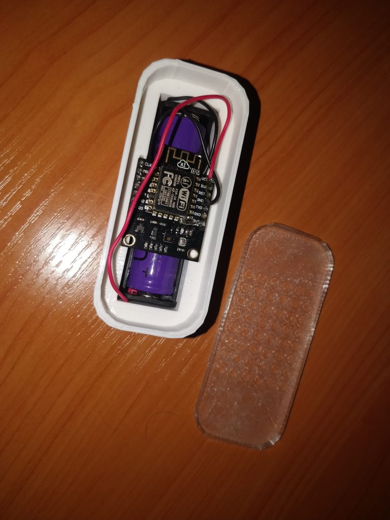
Let’s print a case
For this print I decided to test a combination of PLA+SBS. Pla makes a hard main frame, SBS makes a flex cover that tightly fits with no screws required.

Profit (Where the heck is it?)
The most awesome part of this solution (if not the bugs I wrote above) would have been using a fully off-the-shelf solution, with no need to lay out a board or solder (almost) anything. Besides the sensors are small and tricky to solder. And all that for a price comparable with Aqara sensors.
So, there’s the price breakdown
- 11.25$ * N + 2.25$ shipping for N ESP14S dev boards.
- 0.76$ * N for N 18650 enclosures
- 2-3$ – 18650 power cell
- 3d printed case. Cheap if you own a printer.
The bad stuff, well, plenty of it. The biggest showstopper is the deep sleep not properly working and the whole thing heating up like hell. This screws up all temperature readings and kills battery life.
Besides, there’s no way to get battery voltage without heavily modding the PCB.
Finally, the size of this thing. It’s a brick thanks to 18650 cell. I should’ve used a smaller battery, but I had a bunch of 18650 and cases, so I decided to use those.
P.S.
Looking at aliexpress, I found another ‘great’ solution from that DIYMore:
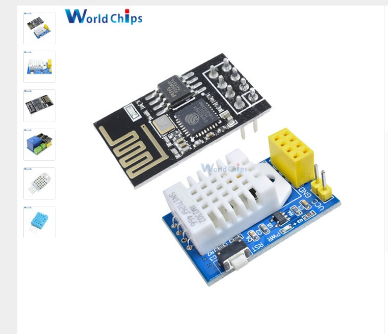
A board with the most precise sensor will set you back for 4.5 bucks, that’s twice cheaper than Aqara’s sensors. Problem is: No battery, another linear waterboiler voltage stabilizerm and the esp8266 module covers the air flow to the sensor. Well, at least you can bend it here.
Looks, like I’ll end up laying out my own sensor board “with blackjack & hookers” (c) Bender.
P.P.S. Where to get the goodies?
- My firmware for STM8 & esphome configuration
- 3D Printed case design files
One thought on “Trying alternatives for Aqara temperature sensors”