This small tutorial will cover how to clone complex 2d parts with a flatbed scanner, inkscape and freecad. You may use this for any complex shapes that are too tough to measure using calipers. This technique can also be used to reverse-engineer complex PCB shapes to aid in creating custom enclosures. As a small example I’ll clone part of my archery fingertab.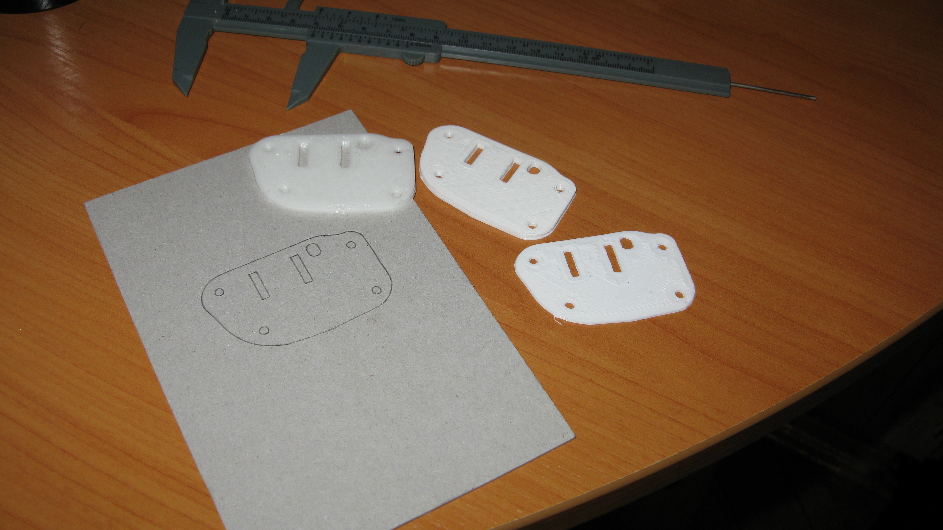
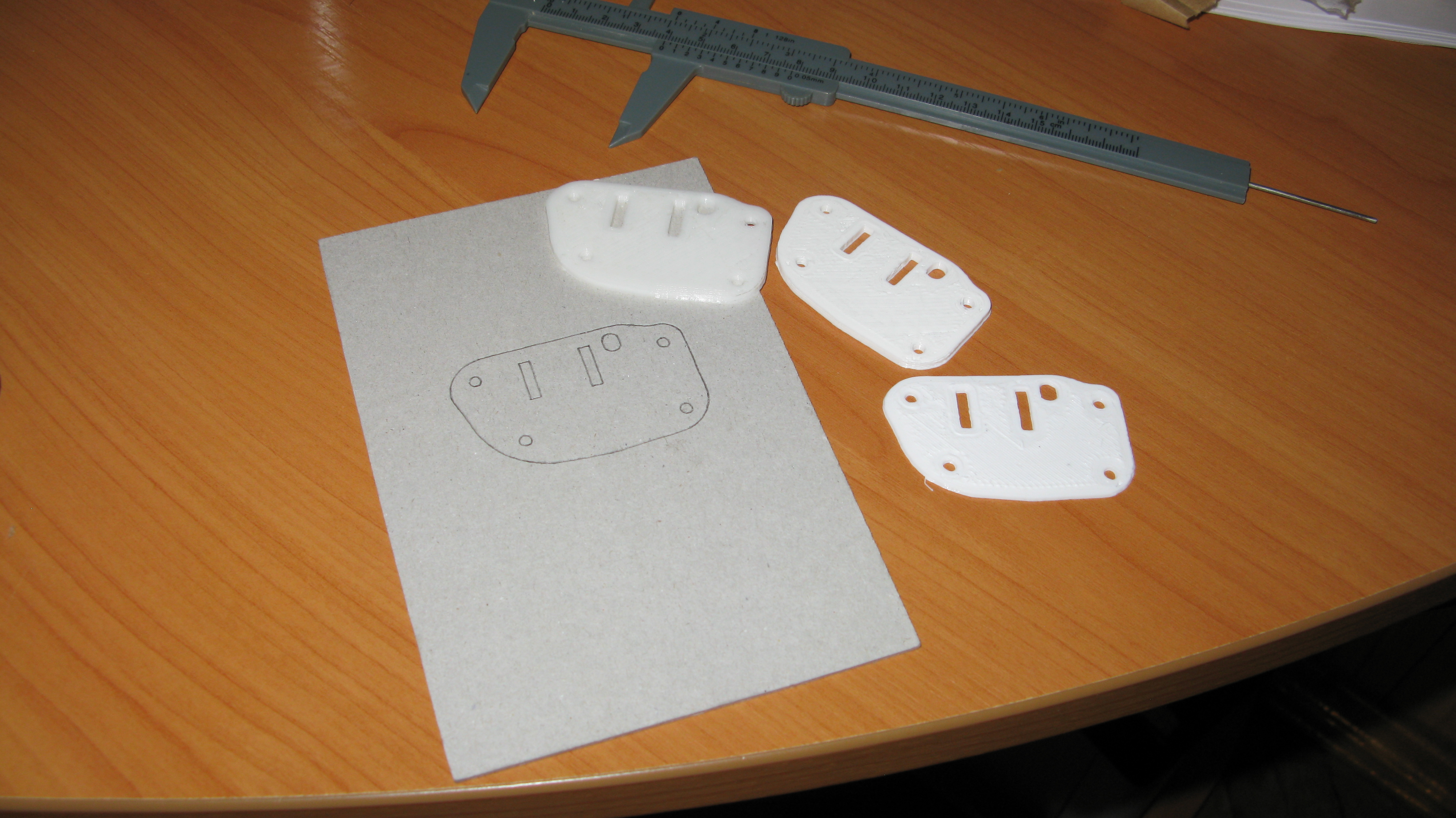
Okay, let’s move on. First we’ll need a piece of paper or cardboard and pencil and trace our shape. Or you can put the part directly under the scanner. It all depends on the color and material of the part and the desired results. I prefer to trace it to avoid scratching the scanner.
The next step is scan it. Preferably pick PNG for less compression artifacts and a relatively high DPI. I picked 300dpi, but it’s mostly a matter of taste and performance. If the cardboard or paper isn’t quite white (Like the one I took for this tutorial) play with contrast and brightness sliders to make it appear whiter. Here’s what I got after scanning and playing with sliders: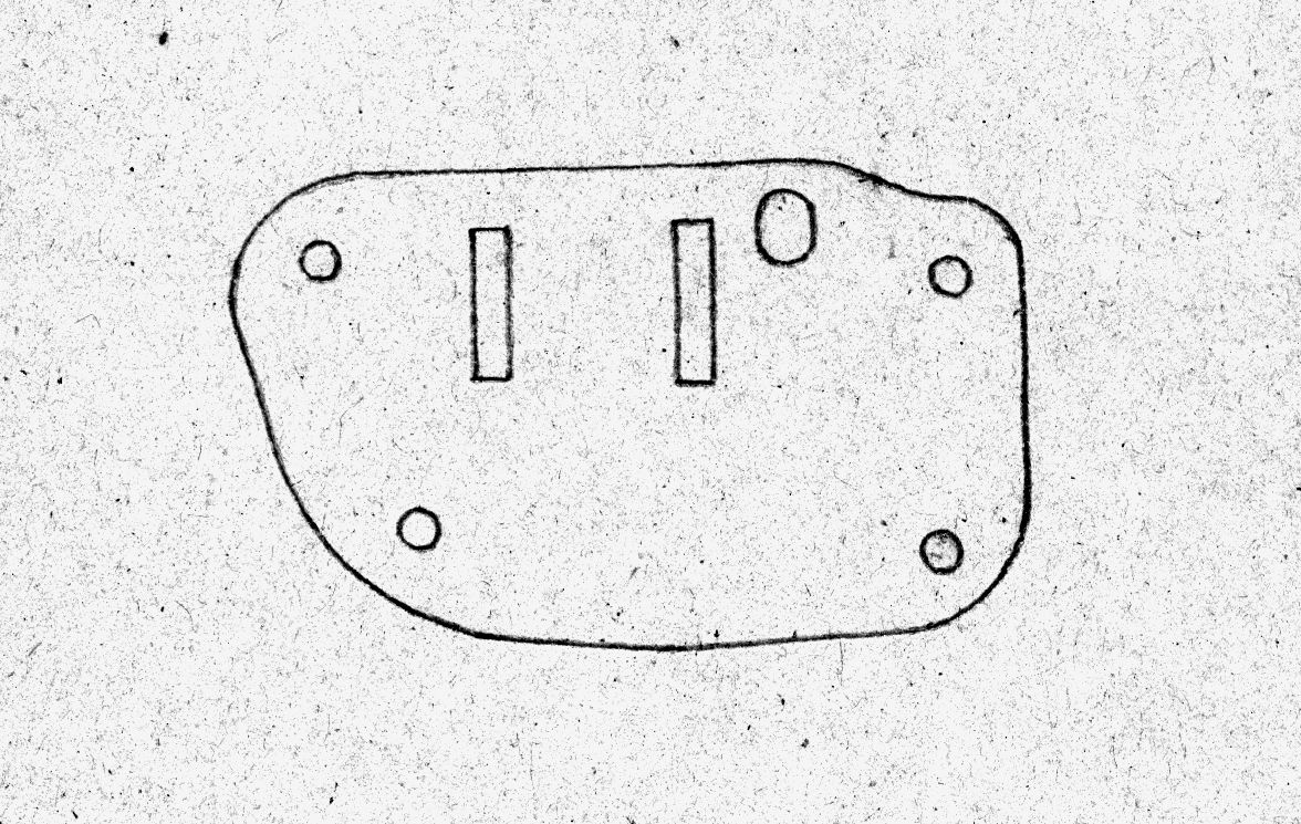
Now import (File->Import) this stuff to inkscape. For PNG the DPI should be saved in the file, but to make sure – you can draw a line, see how long it is in mm and compare it with the ‘real thing’ using calipers. The results should be a precise match unless you scanner software screwed up DPI setting somehow. If you need extra fine results you can calibrate your scanner using some part of known dimensions and calculating the scaling coefficient. But in my case it was already good enough out of the box.
Now we need to trace the bitmap into vector graphics. This procedure will give us precise path and remove all remaining noise. Select the image and click Path->Trace Bitmap. In the dialog we’ll see something like this:
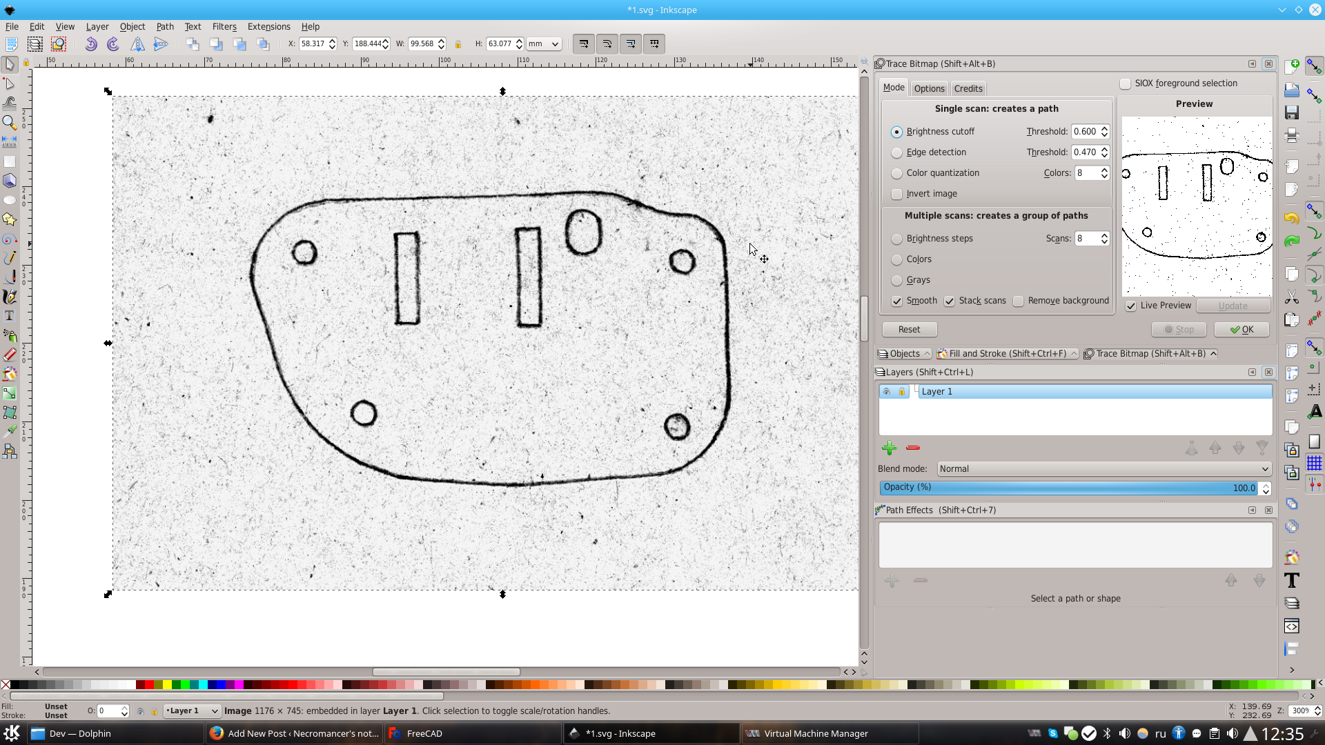
I picked ‘Brightness Cutoff’ mode with a threshold of 0.6. Note the noise dots in the preview window! If your paper is dirty or you are using some non-white cardboard (like in my case, I picked it to show the speckles removal option in action) or if you scanner is dirty or scratched. Gladly inkscape can get rid of those. just navigate to Options tab and configure the ‘Suppress Speckles’ option. The size is dependent on the DPI and it may take a few tries. Note that for some reason this option has no effect on the preview window!
Once traced, we can get rid of the bitmap and fine-tune the traced result. This is what I got:
To remove artifacts along the lines click Path->Simplify. This will remove unneeded points that is also good in terms of performance for further steps. We can do simplification several times, but it has a nasty side-effect of rounding corners.
Almost done. Now navigate to Object->Fill and Stroke. In the ‘Fill’ tab we disable color filling, in the ‘Stroke’ tab we enable the contour. The Freecad manual recommends “Stroke width” parameter set to 0mm, but since we want to see at least something in inkscape now I’ve set it to 0.1mm:
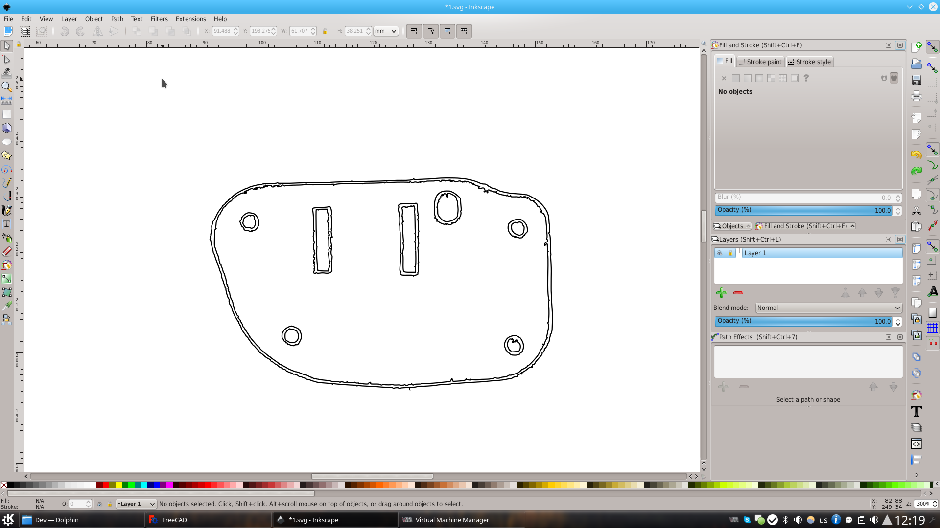
Now every like is split in two. We need to remove the extra. At this point we can pick either the outer or the inner boundary. But before we can do this, we’ll have to click Path->Break Apart.
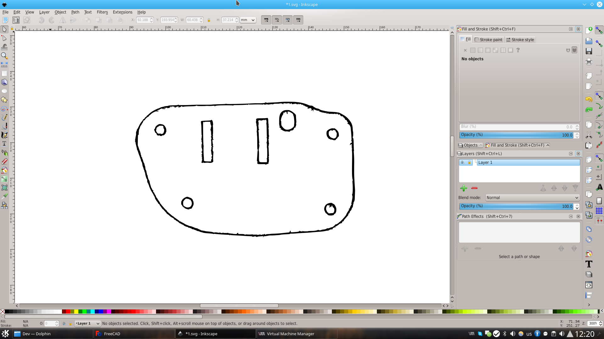
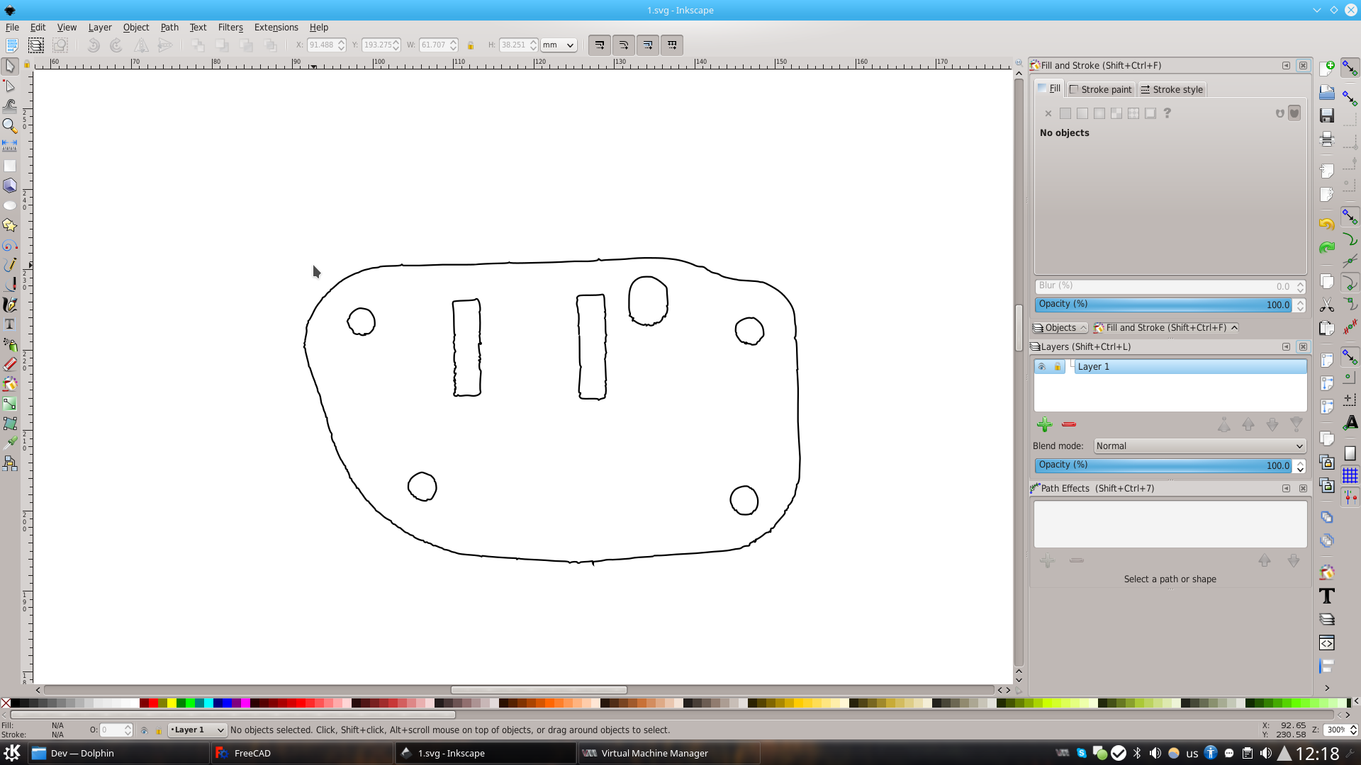
After cleaning up we’ll get a nice shape you see on the picture below. At this point we can go ahead with FreeCad export, or redraw some elements (e.g. circles and rectangles) by hand. Personally I decided to skip this part.
 Now optionally set ‘Stroke Width’ to 0 and save as ‘Plain SVG’. Despite what FreeCad manual says I had no problems importing svg with 0.1mm outline.
We can exit inkscape now, the job is done. It’s freecad time now. Initially I wanted to use solvespace, but dxf import from inkscape (R12 and R14 formats alike) is termally broken: either (R12) sizes are screwed up (and solvespace lacks scaling tool) or there are terrible artifacts around the border (R14). Besides, if there are too many points solvespace refuses to work correctly with the layer considerable slows down. Hopefully it will be fixed in some later releases.
But while now we’ll have to use some ‘heavy artillery’ called FreeCAD. The latter allows to do way more than SolveSpace, but has very counter-intuitive (IMO) interface. Although, I guess, it’s more a matter of habit.
Create a new project in FreeCad and import our SVG as geometry. We’ll end up with something like this:
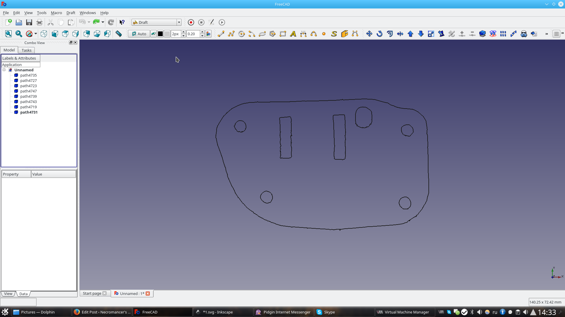
Pick the ‘Draft’ workbench, select all pieces of the puzzle and click ‘Draft->Upgrade’.
Now switch to ‘Part’ workbench. Select all once again and click ‘Part->Extrude’ and pick the desired thickness of the part. We’ll end up with something like this:
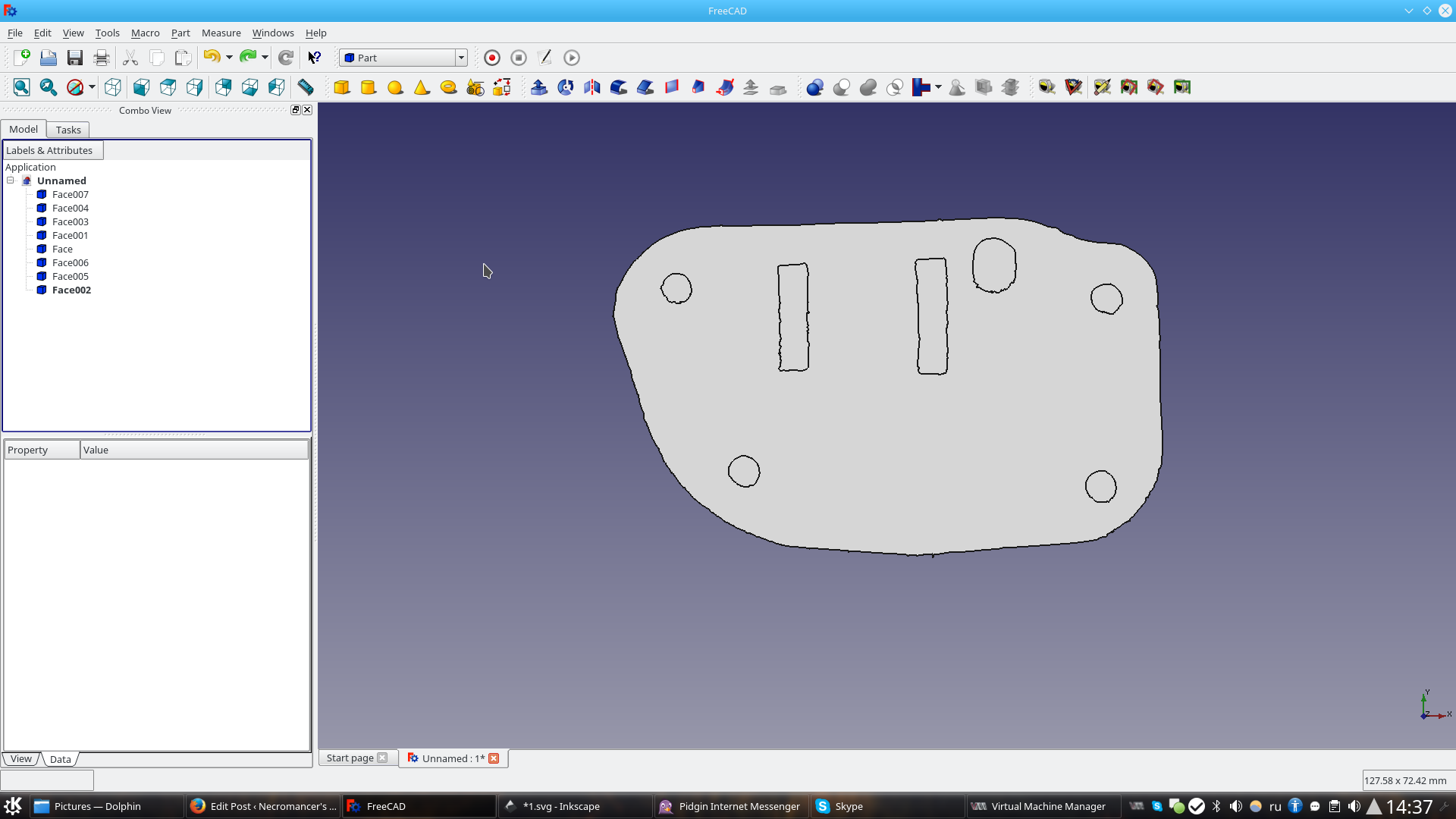
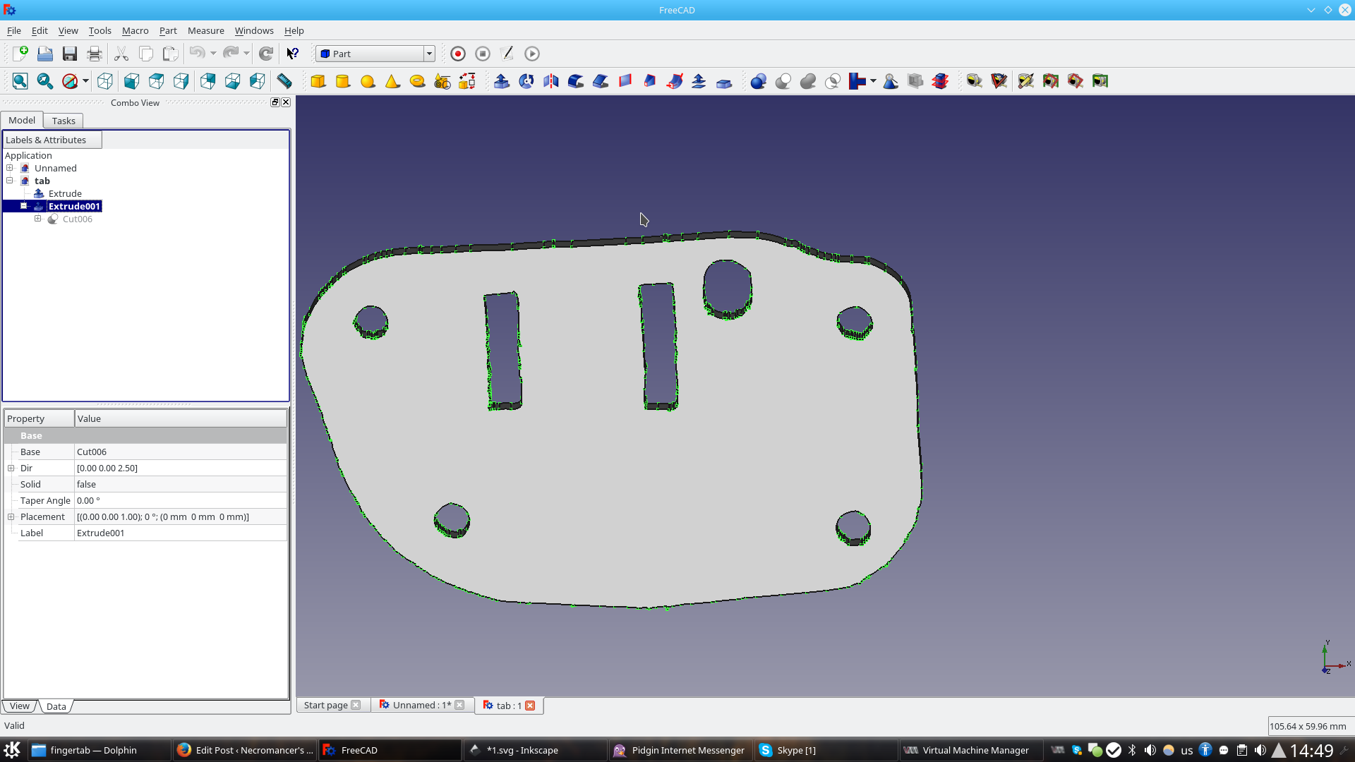
The only thing we’re missing – holes where they have to be. We have to select in turns the main part and the pieces we want to subtract from it and click ‘Part->Boolean->Cut’. After a few iterations we’ll end up with a model that we can finally export to STL:
And, finally, print!
The best part of it that we can easily scan some PCBs and other stuff and that will aid us in designing enclosures (mainly by saving time on the frustrating calipers measurement and re-printing the whole part when we made a single mistake)