One day I needed to add an automated light near the stairs. Motion sensor was already in place, I only needed some bulbs I could turn on and off remotely and I was not feeling like doing any DIY that time. So I picked a few ZigBee bulbs with Е14 socket. What could possibly go wrong here?
The Chinese guy sent me WiFi bulbs instead of ZigBee. Xiaomi Philips. Those are hooked to Xiaomi cloud via Mi Home. For the most adventurous, token can be extracted from the Xiaomi Cloud to drive the bulbs directly from Home Assistant. That was precisely what I’ve done. However those bulbs didn’t work very stable. They were slow to turn on and off, lost WiFi connectivity occasionally and froze every few weeks.
Things weren’t much better with Xiaomi Cloud connected, save for the huge data roundtrip to China and back every time you need to turn on a freaking lamp. The problems weren’t too critical for me to fix the issue and they worked for over a year. However a few days ago when those didn’t turn on at night I understood my patience is finally over and it’s time to fix the issue for good.
Basically, people have done that before. Tasmota fans disassembled the lamps, found GPIOs and posted proper UART wiring. Hardcore esphome fans created a ready-to-use configuration template.
When I understood that those bulbs can’t be flashed “over-the-air” into esphome and I would have to disassemble those, I ran into a few problems:
- There was no manual on how to disassemble the lamp without turning it into scrap metal (Like in this guide);
- The existing esphome code didn’t turn off “cold white” when the lamp should be completely off.
So I rolled up the sleeves, turned on the soldering iron, picked up a few screwdrivers and began the ‘dirty work’ ™.
Disassembly
We’ll need a paper knife, a few screwdrivers of varying sizes and a bit of luck. The whole thing was definitely never meant to be user-serviceable.
First we need to insert the knife under the lens and carefully move it around the bulb. One of the bulbs was hold together by plastic clamps only, the other had traces of glue. No way to tell the difference. Meanwhile, pick a place where it’s easier to put in the screw driver.
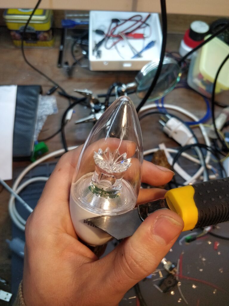
A first inserted a smaller one, then the bigger.
Next it’s a matter of turning the scredriver 90 degrees and off it goes.
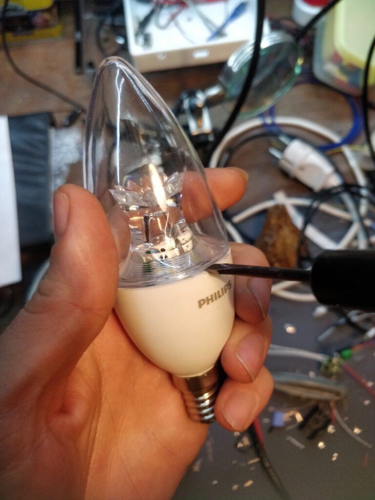
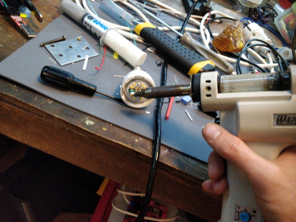
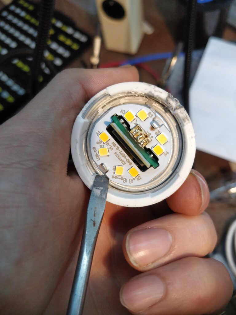
Once we have it open we see the aluminum led panel soldered in place. We’ll have to remove the solder. We can use either the soldering iron and copper wires or use a desoldering tool.
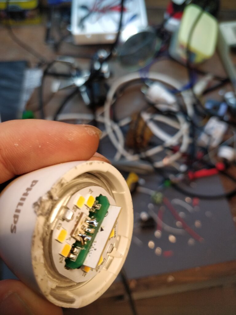
Warm up the thing and remove the solder.
Make sure there are no solder bridges, even small like on the picture below.
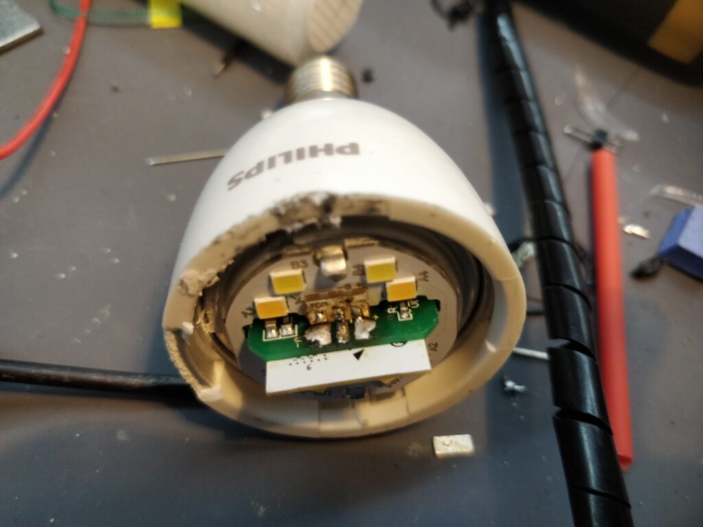
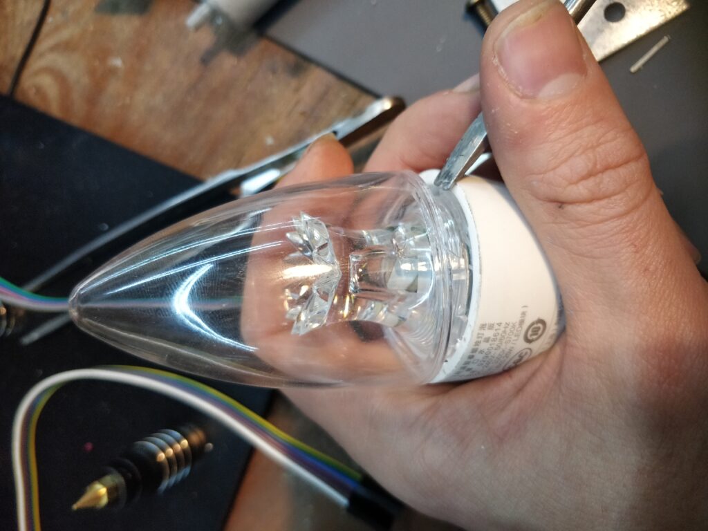
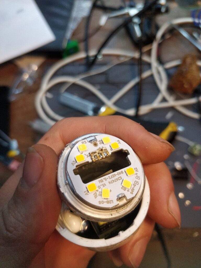
Now we can carefully remove the aluminum place. Pick the screwdriver and carefully pick it all around the bulb.
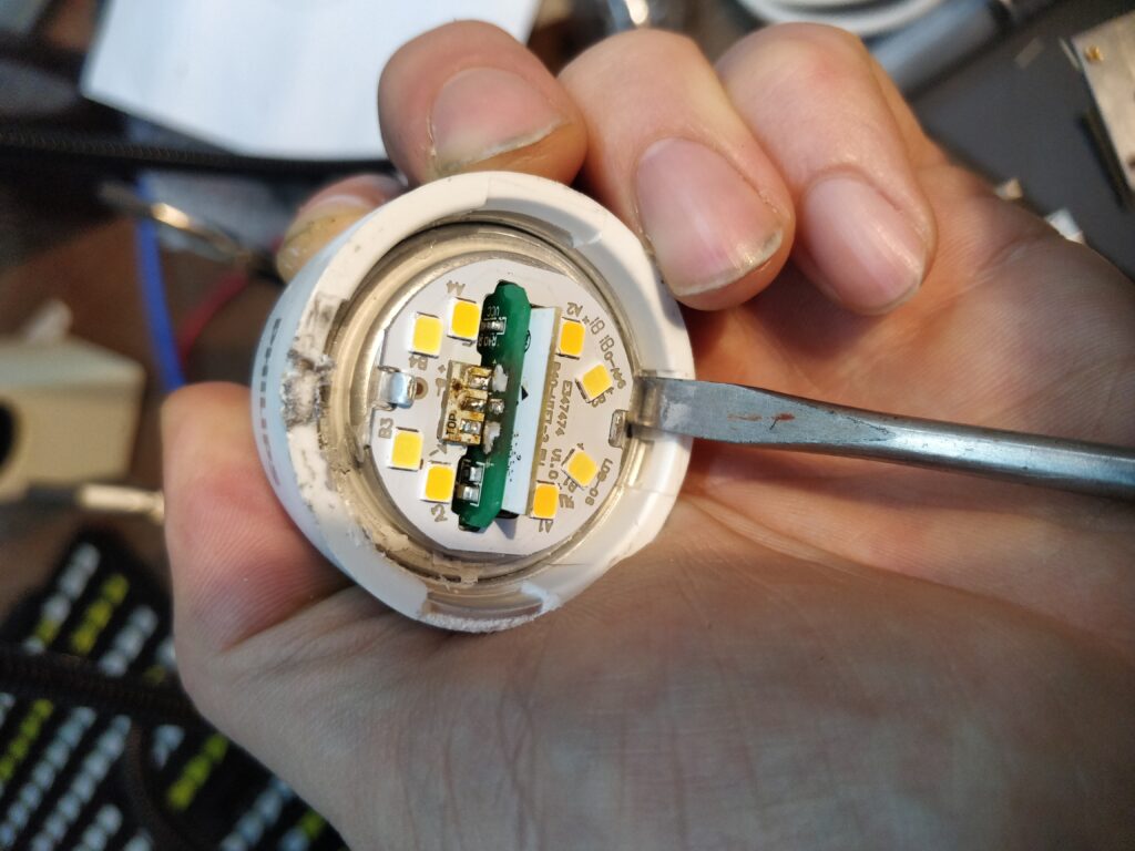
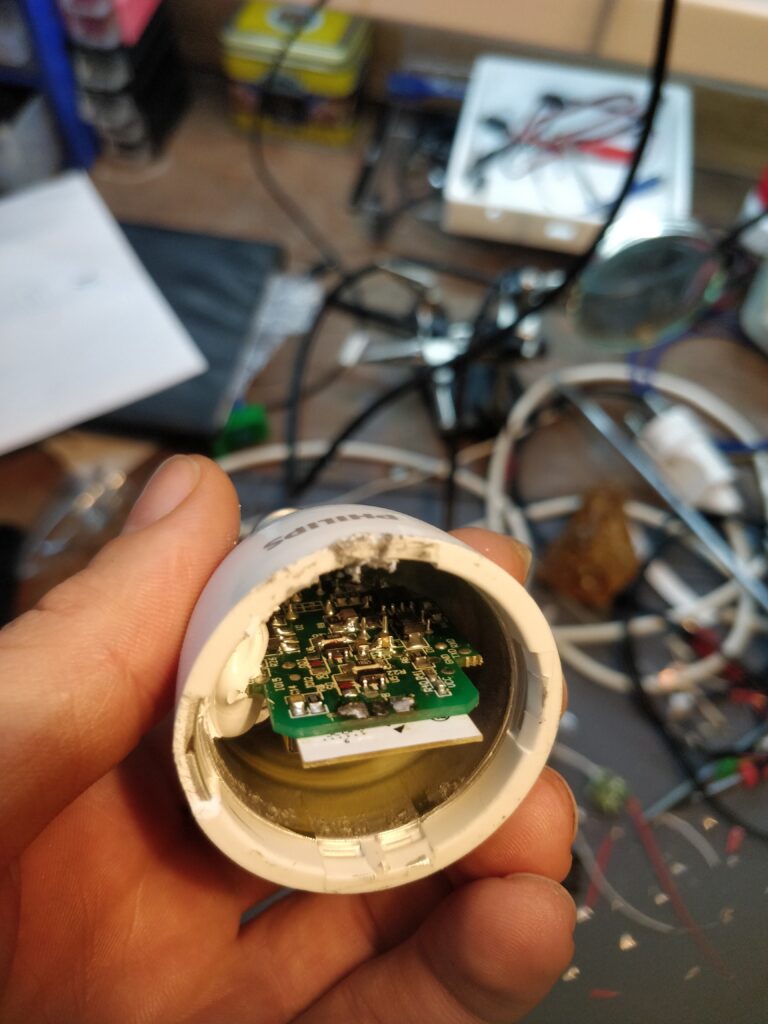
Finally! We now have access to the electronics. Partial.
Remember the old joke that assembling “ships in bottles” – is a job for retired proctologist? That’s what we’ll have to do now, since we can’t remove the electronics from the housing any more. It’s glued forever and ever there.
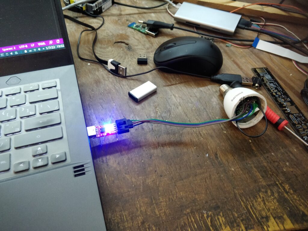
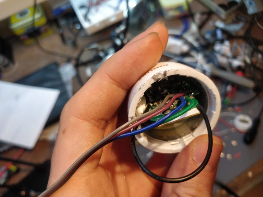
Ffrom my experience it best to drop a little solder on the test pads before soldering the wires. We’re lucky the test pads have distinct labeling. We need our usual pins: RX, TX, GND, VCC and IO0.
VCC should be supplied with 3.3 volts, IO0 wired to the nearest ground pin.
The patient is now lying belly-open and we can start our ‘treatment’ from the curse of the clouds by flashing it with either esphome or tasmota. Luckily, we only have to do it once with further updates delivered over-the-air.

esphome configs
Esphome configuration was first developed by @Sergey-SRG. It was later forked, updated and improved by @syssi. His repo works for the latest esphome versions. However “cold white” never completely turned off on my bulbs out of the box. So I had fork the repo and throw in some improvements. The code is available in my fork and also submitted via a Pull Request.
Bonus: Thermistor
The weird people shoved a fullblown RTOS on a lightbulb! Boom! An operating system on a lightbulb! I guess one day we’ll even see docker running on those. (Read that with the voice of John Stewart!). It even has an interactive console via UART, found by Tasmota fans. Let me quote that:
help
reboot
restore
setwifi ARG: <"ssid"> <"passwd"> RET: ok/ error
getwifi ARG: none RET: <"ssid"> / error
gettemp ARG: get temperature data
stop_mcmd ARG: stop miio cmd RET: none
model ARG: <model_string> RET:
getversion ARG: get firmware version
getheap ARG: get heap: ok/error
mac ARG: none RET: ok/error
bri ARG: bright pwm test, 0-100 RET: ok/error
cct ARG: cct pwm test, 0-100 RET: ok/error
setcct ARG: cct control test, 0-100 RET: ok/error
setbri ARG: bri control test, 0-100 RET: ok/error
setbricct ARG: bri and cct control test, 0-100 RET: ok/error
applyscene ARG: apply scene: ok/error
I quickly noticed the gettemp ARG: get temperature data line. If I were a Chinese engineer designing those bulbs I’d put a cheap thermistor on the only ESP8266 ADC pin to measure the bulb temperature and avoid overheat. I added ADC readings to my config and, as I expected, I saw numbers going down when the bulb heats up. However there was no way to find out exact values without tearing the bulb apart.
Playing with numbers I’ve guesstimated the divider resistance to be 500kOhm, NTC to be 100kOhm and picked the same coefficient that 3d-printer temperature probes had. I calibrated the readings by a “gentle touch”, and watched the temperatures rise from 30 to 40 degrees on maximum brightness. Finally, I’ve added a failsafe to reduce brightness by 10% every time the temperature is above 55 degrees like the one below:
light:
  - platform: custom
    lambda: |-
      auto light_out = new XiaomiLight(id(out_cw),id(out_b));
      App.register_component(light_out);
      return {light_out};
    lights:
      - name: $hostname Light
        id: TheLight
        gamma_correct: 0

sensor:
  - platform: ntc
    id: the_ntc
    sensor: resistance_sensor
    calibration:
      b_constant: 3950
      reference_temperature: 25°C
      reference_resistance: 100000
    name: "$hostname NTC Temperature"
    on_value:
      if:
        condition:
          light.is_on: TheLight
        then:
          lambda: |-
            float brt;
            id(TheLight).current_values_as_brightness(&brt);
            if (x > 55) {
              brt -= 0.1;
              auto cl = id(TheLight).turn_on();
              cl.set_brightness(brt);
              cl.perform();
              ESP_LOGD("NTC", "Overheat! Decreasing brightness to %f", brt);
            }
  - platform: resistance
    id: resistance_sensor
    sensor: source_sensor
    configuration: DOWNSTREAM
    resistor: 500000
    reference_voltage: 3.3
    name: $hostname Resistance Sensor
    internal: true
  - platform: adc
    name: "$hostname RAW ADC"
    internal: true
    id: source_sensor
    pin: A0
    update_interval: 60s
    filters:
      - median:
          window_size: 3
          send_every: 1
          send_first_at: 1
If someone has one of those bulbs completely torn apart and can share the photos, please let me know, I’ll update the configs to better reflect the reality.
Finale
After operating the patient’s recovery was swift. No more disconnections, fast reaction times. Everything looked great. The thirst for a cloud connection using Mi Home with “Mainland China” in the App Settings was also gone for good.